// Overview
Project Overview
An autonomous Airborne Guidance Unit (AGU) that navigates a 5kg payload to a designated GPS coordinate. The problem it solves: high-altitude scientific payloads frequently drift off-course during unguided descent.
The system is a custom 4-layer PCB with a high-fidelity RF/inertial sensor suite and a GNC algorithm running on FreeRTOS. During field validation, it navigated from a 75-meter drop, correcting for wind shear, to land within a 5-meter radius of the target.
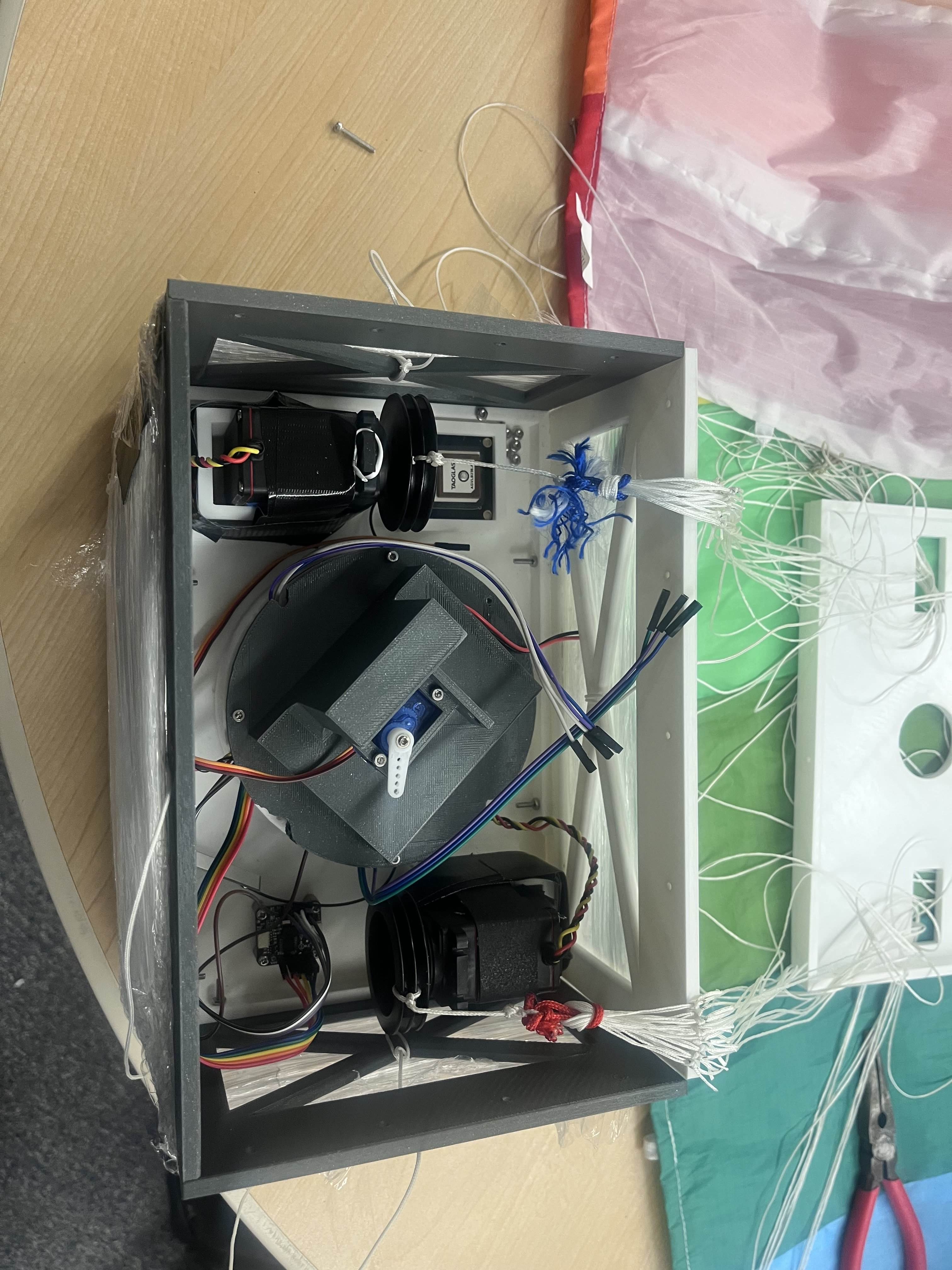
AGU chassis & actuation rigging
// Flight Test
Flight Validation
2025-12-06 · drop altitude 75m · wind moderate
AGU detects freefall via the IMU, stabilizes the payload, and begins actuating the left/right brake lines to execute calculated heading corrections against the wind vector. Final touchdown occurred <5m from the target coordinate.
// Hardware
Hardware Architecture
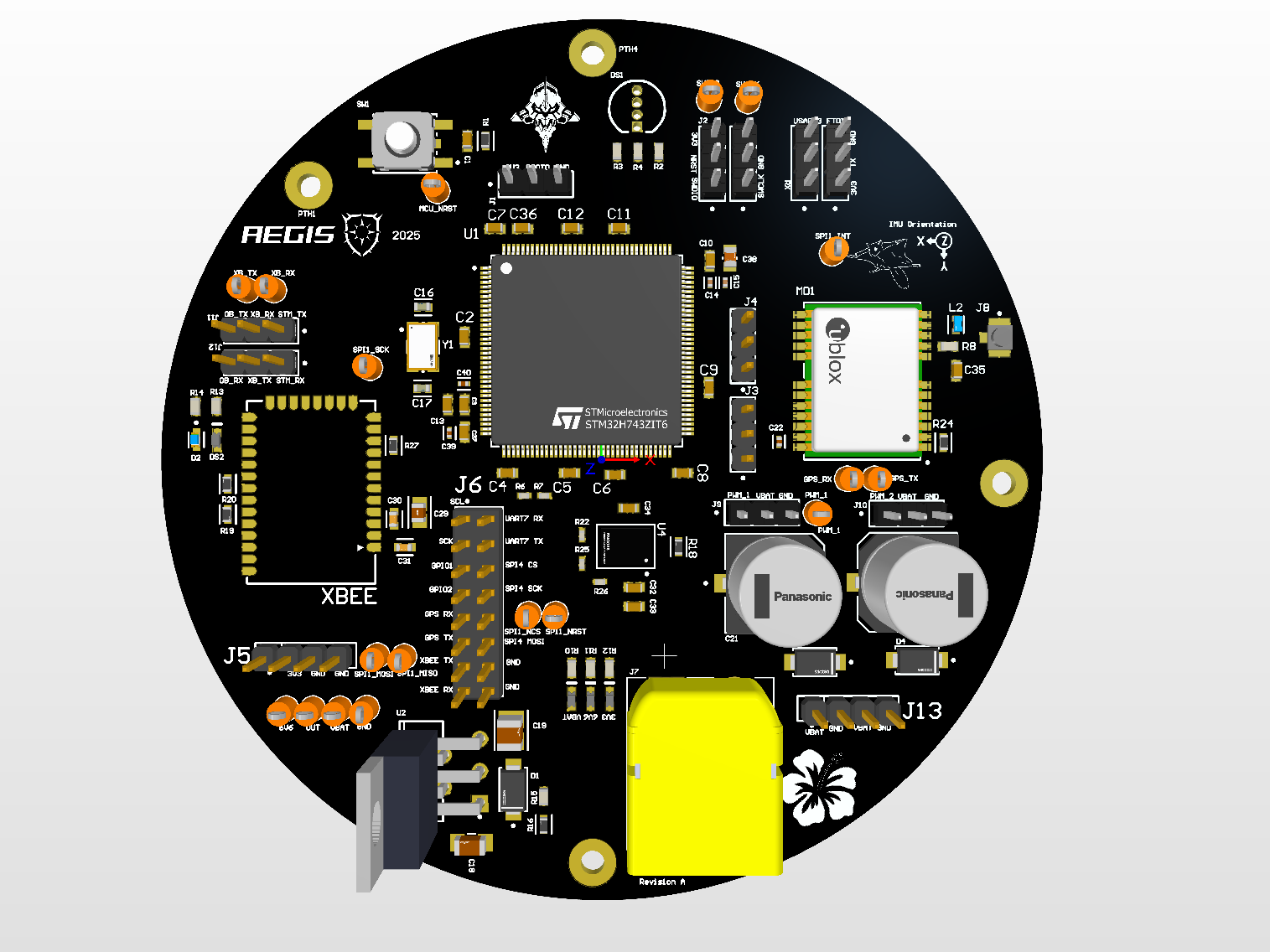
click any image to inspect at full resolution
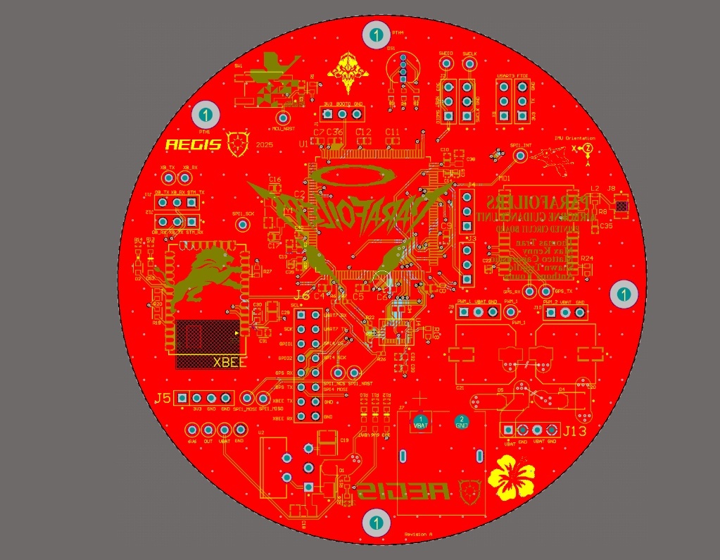
Layer stackup & EMI shielding
A Ground–Signal–Power–Ground stackup shields internal high-speed digital traces from external EMI, which matters for the onboard RF modules. Inner layers use 2oz copper to handle high-current transients from the servo motors without severe thermal rise.
Power distribution — star topology
A star routing topology isolates the noisy servo power rails from the sensitive 3.3V logic rails. Prevents inductive ground bounce and voltage sags from servo stall currents resetting the STM32 core during stall flight maneuvers.
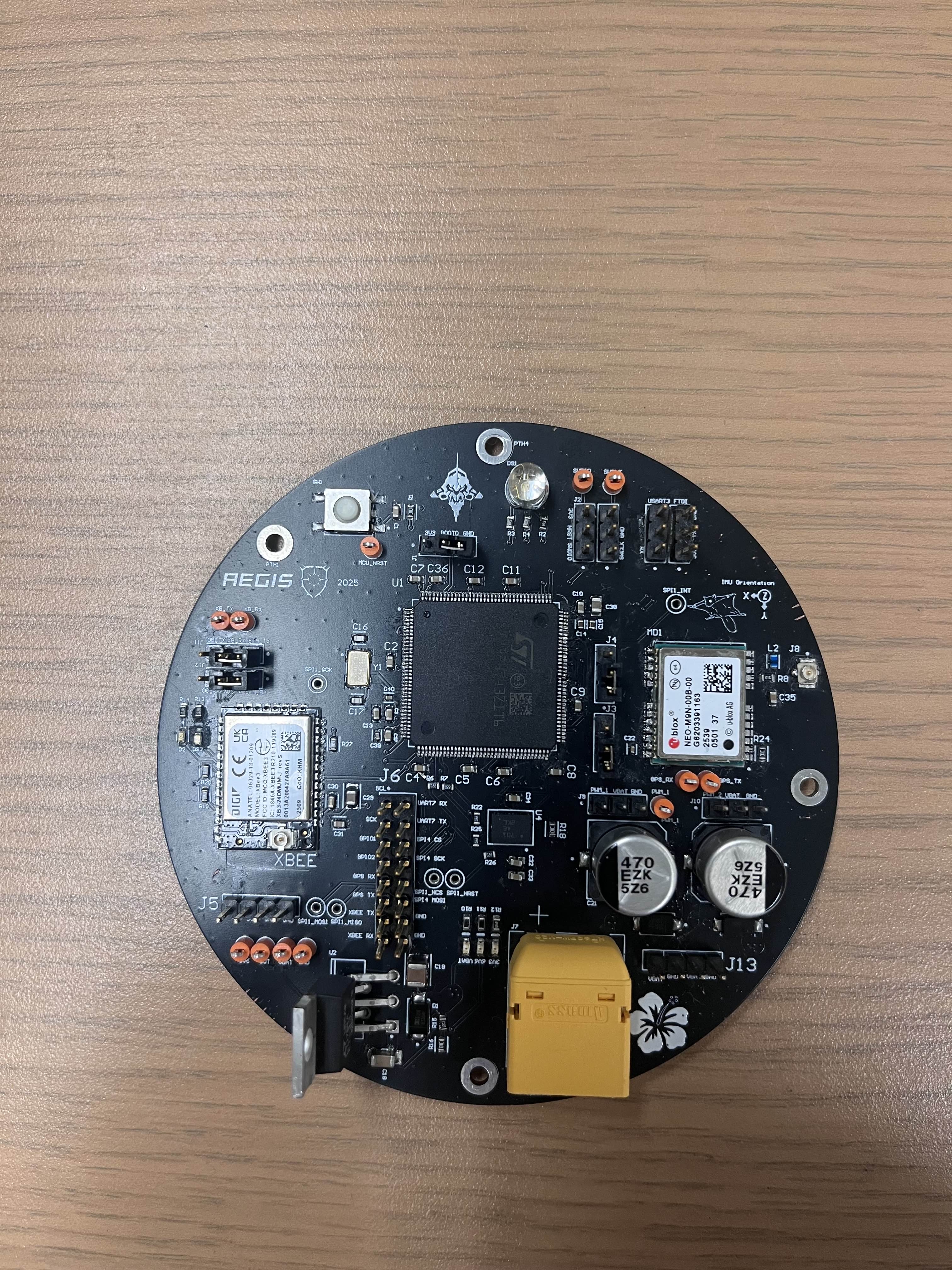
Active RF front-end
A NEO-M9N GNSS receiver paired with a custom bias-tee circuit (27nH inductor + 100nF capacitor network). It injects clean, low-noise DC power via an LT1764AET-3.3 LDO into the active antenna coax while isolating the RF path back to the receiver.
// Firmware
Firmware & State Estimation
RTOS architecture
Bare-metal firmware on an STM32H7, with FreeRTOS managing asynchronous sensor pipelines.
- → Task_IMU (100Hz) — high priority. Polls BNO085 via custom SPI driver. Handles SHTP protocol fragmentation/reassembly for zero data loss.
- → Task_GPS (DMA) — parses binary UBX packets directly from UART via DMA. Extracts V_NED vectors without blocking CPU cycles.
7-state EKF
A 7-state Extended Kalman Filter targeting position, velocity, and heading bias. To optimize for the MCU's FPU, I used a sequential update formulation, processing GPS measurement scalars independently and bypassing matrix inversions during the update step.
failsafe
Continuous geofence and sensor-health monitoring. Breaches trigger a hard "deadspin" interrupt, forcing servos into a rapid spiral descent to prevent fly-aways.
Control flow
execution rate: 100Hz
// Documentation